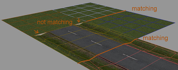
Matching
and mismatching tiles
The track piece P3D
There are four possible sizes for track pieces. Tile extensions of either 20x20m, 40x40m, 20x40m or 40x20m are supported. The “main” mesh which is responsible for the tile's bounding box and collision detection has to meet exactly one of these four extents!
Track tiles can consist of a various number of meshes. However it is only recommended to "split" parts of a track piece away from the "main" mesh into a seperate one it makes sense: for instance, if you like to add breakable or explosive elements to the track piece. "Level Of Detail" is supported and recommended to be used for track pieces, especially on the usually high-poly "main" mesh (see Level Of Detail implementation).
Special meshes are recognized by special mesh names. Below you see a list of different types of breakable meshes
|
Mesh name |
Description |
|
gls_* (e.g. “gls_wind“) |
smashable window and glass meshes |
|
plas_* (e.g. “plas_frame“) |
smashable plastic object in track piece |
|
wood_* (e.g. “wood_fence“) |
smashable wood object in track piece |
|
metl_* (e.g. “metl_fence“) |
smashable metal object in track piece |
|
expl_* (e.g. “expl_barrl“) |
explosive object in track piece
NOTE: |
Modeling
Matching
and mismatching tiles
In Crashday tiles will only be seamless if their borders are exactly matching to each other. For instance, this means that you can build a planar tile next to another one in the track editor without creating any ugly seams. However, you cannot simply combine a road with a planar tile (now the seams will appear!). The solution for this engine-specific issue is to create a "converter tile" that fades tile A into tile B properly. Be sure to respect this circumstance when building custom tiles.
(Un)fortunately Crashday offers tracks with more than just flat terrain. This aspect has to be considered when creating custom track pieces. Before starting modeling
you should make yourself clear about whether you want your tile to be "bendable" if placed on curved terrain or not. If yes, subdivision vertices have to added each 5 meters along both
horizontal directions (namely the X and Z axis). Given these vertices and bending enabled, you tiles will look smooth on curvy terrain and drive a lot better.
A
typical example of a tile without bending restrictions is a planar ground tile. In this case, the model has to be subdivided both in X and Z direction.
Another case is a road tile for example, where you will probably want to avoid bending the both driving lanes away from each other, but allow bending along the driving direction (to make the road go up/down smoothly).
Finally, in the situation of creating a building you will probably not want to make it bend in any direction at all.
Smoothing
groups Different
from car-.p3d's, smoothing groups are not really supported by
track pieces. In fact you only can set one, and only one, smoothing
group (SG). All faces holding this SG will be smoothed together, the
remaining polys will appear flat shaded in-game (they need to have "no smoothing group" assigned). Construction checklist Below
is a checklist what has to be taken care of, when creating track
pieces Be
sure track pieces “main” mesh meets one of the four
dimensions: 20x20m, 40x40m, 20x40m or 40x20m As
the “main” mesh is also responsible for collision
detection, make sure it has sufficient but not too much detail Be
sure to use “level of detail” meshes where useful (see Level Of Detail implementation)
AI
usually needs AI nodes placed in the center of tiles. Respect this when
creating road tiles (see AI driver information for AI node setup) Make
sure no gaps will come up between tile borders when combining
track pieces Subdivide
your track tiles every 5 meters in X/Z direction if possible When
modelling below 0-height use special parameter provided by
MakeP3D (see MakeP3D) Make
sure polygons are only using one single or no smoothing group at all Texturing You
can either use Crashday's default textures and/or add your own
.dds/.tga-files. The complete list of textures, used by track tiles,
has to be placed into [crashday]\textures. Please refer to Textures and shaders for more information on how to use textures
and shaders in-game.
All of these three cases are illustrated below (see Tile specification file
for setting up bending restrictions, see Track piece reference models for example
.max/.3ds files)
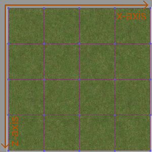
Plane
field tile, subdivided in X/Z axis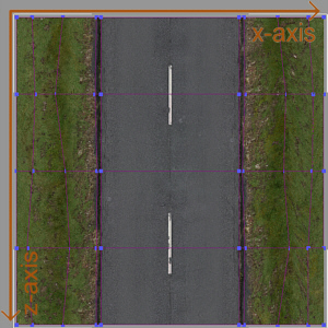
Road
tile, subdivided in Z axis only (X axis bending disabled)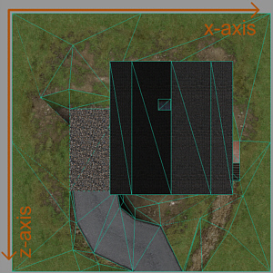
House
tile, no subdivision
 The
lowest vertex in the "main" mesh (in vertical y-axis) defines the lower bottom of the tile bounding box. This bottom is used as a measure to align the tile to the heightmap vertically in-game. Usually the lowest vertex
is the ground plane where this technique works well. However, in certain situations you might want to create vertices that lie below ground level (such as tunnels). See the MakeP3D documentation on how to convert models
with vertices below ground level that don't effect the bounding box
The
lowest vertex in the "main" mesh (in vertical y-axis) defines the lower bottom of the tile bounding box. This bottom is used as a measure to align the tile to the heightmap vertically in-game. Usually the lowest vertex
is the ground plane where this technique works well. However, in certain situations you might want to create vertices that lie below ground level (such as tunnels). See the MakeP3D documentation on how to convert models
with vertices below ground level that don't effect the bounding box